Step 1. S-Parameter Hardware Measurement Control
Hardware Setup
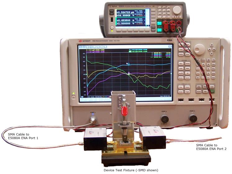
Setup the PD1000A S-parameter hardware as shown in the two graphics below. For complete details on setting up the test instruments, see the PD1000AStartup Guide.
The same basic setup is used for all three device test fixtures.
For specified accuracy, always allow the test instruments to warm up for a minimum of one hour before testing.
Set/Verify the B2902A/B Power Line Frequency
See: Set/ Verify AC Line Frequency and Date/Time on the B2902A/B
Prepare to run the S-Parameter Tests
- Connect the test fixture (either the TO-220, TO-247, or the SMD test fixture) to both PD1000A Bias T Networks.
- Connect the Bias T Networks (which are required for on-state measurements) to the B2902A/B Source Measurement Unit (SMU) as shown below.
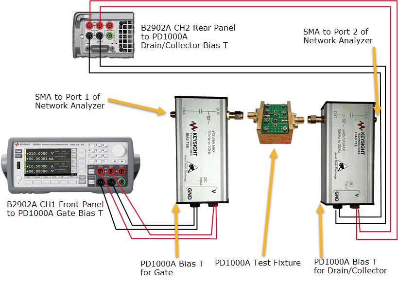
- Using two SMA cables and the SMA to N Connector adapters, connect the two Bias T Networks to the E8050A ENA Network Analyzer.
Do not calibrate the test fixture until you are ready to run your S-parameter measurements. Calibration depends on the specific DUT under test and the network analyzer and SMU settings that you choose for that DUT.
Next Steps:
Step 2. Configure S-Parameter Settings